Piston Rod Size Selection
- home
- Piston Rod Size Selection
Manufacturer, Supplier and Exporter of Hydraulic Cylinders, Hydraulic Power Packs, Power Pack Units and Systems, Tie Rod Type Cylinders, Heavy Duty Cylinders-004, Mill Duty Type Cylinders-004, Welded Type Cylinders-004, Hydraulic Telescopic Cylinders, Fly Ash Bricks Making Machines, Piston Rod Sizes and Stop Tube, Double Ended Hydraulic Cylinders-003, Pune, Maharashtra, India.
The selection of a piston rod for thrust (push) conditions requires the following steps to be carried out:
- Determine the type of cylinder mounting style and rod end connection to be used. Consult the Stroke Factor table and determine which factor corresponds to the application
- Using the appropriate stroke factor, determine the 'basic length' from the equation : Basic Length = Net Stroke Factor (The graph is prepared for standard rod extensions beyond the face of the gland retainers. For rod extensions greater than standard, add the increases to the net stroke to arrive at the 'basic length'.)
- Calculate the load imposed for the thrust application by multiplying the full bore area of the cylinder by the system pressure, or by referring to the Push and Pull Force charts
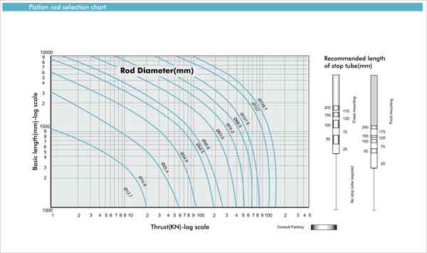
- Using the graph below, look along the values of 'basic length' and 'thrust' as found in 2 and 3 above, and note the point of intersection.
Note - When considering the use of long stroke cylinders, the piston rod should be of sufficient diameter to provide the necessary column strength.
Stop tubes prevent the cylinder from completing its full stroke, to provide a spread between the piston and the rod bearing at full extension. Note that stop tube requirements differ for fixed and pivot mounting cylinders. The required length of stop tube, where necessary, is read from the vertical columns on the right of the graph by following the horizontal band within which the point of intersection lies. If the required length of stop tube is in the region labeled ‘consult factory’, please supply the following:
- Cylinder mounting style
- Rod end connection and method of guiding load
- Bore required, stroke, length of rod extension.
- Mounting position of cylinder. (Note if at an angle or vertical and specify the direction of the piston rod.)
- Operating pressure of cylinder, if limited to less than the standard pressure for the cylinder selected.
The correct piston rod size is read from the diagonally curved lines labeled Rod Diameter above the point of intersection

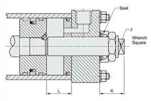
The option of bleed screws, illustrated below, is available at either or both ends of the cylinder, at any position except in the port face. The selected positions should be shown in the order code
On spring-return cylinders, it is recommended that tie rod extensions be specified on the cylinder end in which the spring is located to allow the spring to be 'backed-off' until compression is relieved.
Tie rod nuts should be welded to the tie rods at the opposite end of the cylinder, to further assure safe disassembly. Please consult the factory when ordering spring-return cylinders.
To obtain linear force in one plane with controlled stopping at intermediate points, several designs are available. For three stopped positions, it is a common practice to mount two standard single rod Style H cylinders back-to-back, or to use through-tie rods. By extending or retracting the stroke of each cylinder independently, it is possible to achieve three positions at the piston end. An alternative technique is to use a tandem cylinder with an independent piston rod in the cap section. Please consult the factory for further details.
Where absolute precision in stroke length is required, a screwed adjustable stop can be supplied at the cap end. Several types are available - the illustration shows a design suitable for infrequent adjustment of an uncushioned cylinder. Please contact the factory, specifying details of the application and the adjustment required.
Unprotected piston rod surfaces which are exposed to contaminants with air hardening properties should be protected by rod end bellows. Longer rod extension are required to accommodate the collapsed length of the bellows. Please consult the factory for further information.
Metallic rod wipers replace the standard wiper seal, and are recommended where dust, ice or splashing might damage the wiper seal material. Metallic rod wipers do not affect cylinder dimensions.
These can be fitted to give reliable end of stroke signals.
Linear position transducers of various types are available for AHP series cylinders. Please consult the factory for further details.
These units provide positive locking of the piston rod. They require hydraulic pressure to release, while loss of pressure causes the clamp to operate, allowing them to be used as a fail- safe device. Please consult the factory for further information.
Standard AHP series cylinders are of the double acting type. They are also suitable for use as single acting cylinder, where the load or other external force is used to return the piston after the pressure stroke. Cast iron piston rings should not be used with single acting cylinder.
Series AHP single acting cylinders can be supplied with an internal spring to return the piston after the pressure stroke. Please supply details of load conditions and friction factors, and advise whether the spring is required to extend or return the piston rod.


| Bore dia B H8 | J | Kmin. | Lmax. |
|---|---|---|---|
| 40 | 11 | 85 | 127.0 |
| 50 | 17 | 85 | 127.0 |
| 63 | 17 | 85 | 203.2 |
| 80 | 17 | 85 | 203.2 |
| 100 | 17 | 85 | 203.2 |
| 125 | 17 | 85 | 228.6 |
| 150 | 22 | 85 | 228.6 |
| 200 | 22 | 85 | 458.0 |


